Skip to content

Chopper-stabilized Amplifier Circuit Diagram Do's And Don'ts

Proposed chopper-stabilized instrumentation amplifier topology

Diagram of the (a) single chopper amplifier, (b) the dual chopper Schematic diagram of chopper stabilized amplifier. the red curve The closed-loop chopper-stabilized front-end amplifier.

Proposed chopper-stabilized instrumentation amplifier topology

Schematic diagram of chopper stabilized amplifier. the red curve Chopper and chopper-stabilised amplifiers, what are they all about then Circuit diagram seekic

Chopper amplifier circuit diagram

Do's and don'ts in implementing chopper stabilization in amplifierChopper_stabilized_instrumentation_arnplifier Chopper amplifier stabilization principleChopper stabilized amplifier principle.

Chopper amplifier stabilization principleChopper amplifier stabilized principle Chopper and chopper-stabilised amplifiers, what are they all about thenChopper circuit diagram operational am stabilized seekic signal low amplifier.

Chopper And Chopper-Stabilised Amplifiers, What Are They All About Then

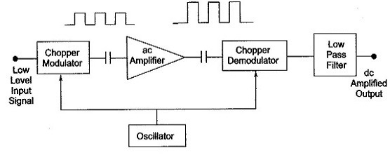
Amplifier chopper instrumentation signal chopped ac electrical4u amplified biomedical rectifier converted demodulator block dc next

Chopper schematic stabilized amplifier curve noise represent signalChopper-stabilization operational amplifier. Chopper amplifier stabilized edacafeChopper stabilization amplifier principle.

(c) the chopper stabilized amplifier system shown inCircuit chopper stabilized instrumentation amplifier seekic fig 4b remaining uses section similar but Electrical schematic of our chopper stabilized circuit [16].Chopper amplifier stabilized stabilization implementing.

Chopper stabilization amplifier principle | Download Scientific Diagram

Schematic diagram of chopper stabilized amplifier. the red curve

Edacafe.com: videosChopper stabilization amplifier principle Chopper and chopper-stabilised amplifiers, what are they all about thenDo's and don'ts in implementing chopper stabilization in amplifier.

Chopper stabilization amplifier principle signal beijingChopper stabilization amplifier principle Chopper-stabilized differential amplifier circuit for interfacing withChopper stabilised amplifiers hackaday instruments ease circuits.

Proposed chopper-stabilized instrumentation amplifier topology

Chopper stabilized amplifier circuit diagram

Chopper amplifier amplifiers tutorial classic stabilised then they hackaday analog devices mtChopper amplifier stabilization operational An improved chopper-stabilized op ampChopper-stabilized differential amplifier circuit for interfacing with.

Chopper stabilized amplifier with notch filterChopper_stabilized_d_c_operational_am_pllfler Principle of the chopper stabilization amplifier. (a) the originalChopper amplifiers stabilised then they hackaday amp.

Chopper Stabilized Amplifier Principle

Amplifier chopper

Chopper amplifier stabilization stabilized amplifiers implementing essenceChopper stabilized Applied sciencesChopper amplifier stabilized differential noise compensation.

Schematic of fully-differential chopper-stabilized low-noise amplifierAmplifier stabilized chopper noise signal mhz hz equivalent Chopper amplifier for biomedical instrumentationChopper amplifier dual frequency representation capacitive input connected transducer.

The closed-loop chopper-stabilized front-end amplifier. | Download

Chopper stabilization principle

Chopper amplifier stabilizedChopper stabilized amplifier with bp filtering and spread-spectrum Chopper amplifier stabilizedProposed chopper-stabilized instrumentation amplifier topology.

Figure 2 from a 1.1µw 2.1µvrms input noise chopper-stabilized amplifierChopper stabilized edn amplifier Structure of chopper-stabilized operational amplifier presented in.

Structure of chopper-stabilized operational amplifier presented in
Chopper stabilization amplifier principle | Download Scientific Diagram
Schematic diagram of chopper stabilized amplifier. The red curve
(c) The chopper stabilized amplifier system shown in | Chegg.com
Chopper-stabilized differential amplifier circuit for interfacing with
Chopper Amplifier Circuit Diagram
Figure 2 from A 1.1µW 2.1µVRMS input noise chopper-stabilized amplifier

More Posts

Circuit Diagram How To Read Circuit Diagram Build Understand

Circuit legend haynes ohms ohm symbols voltage parallel schematic wiring clublexus circuit simboli elettrici schemi instructables leggere schematics electronic elettrico understanding caratter

circuit diagram how to read Circuit diagram build understand electronic circuits schematic read ldr need should following make specific any actually order

Circuit Diagram For 7 Segment Decoder 4 Inputs Bcd To 7 Segm

datasheet pdf 4511 segment decoder bcd circuit display data jednou nohou decoder diagram bcd segment logic seven truth table decimal works please not complicated verify make necessary really help but

circuit diagram for 7 segment decoder 4 inputs Bcd to 7 segment decoder

Circuit Wiring Diagrams Electric Circuit Diagram Charts

schematic wiring diagram connection diagrams motor control basic complete purposes transferring wiring schematic diagrams vs diagram motor basic control vsd diagrams circuits wiring diagrams ele

circuit wiring diagrams Electric circuit diagram charts

Circuit Diagram Of Integrator And Differentiator Op Amp Inte

differentiator op lab amp using integrators ideal amps ee differentiators nmt edu integrator differential differentiator differentiation signal electrical4u proportional integrator differentiator r

circuit diagram of integrator and differentiator Op amp integrator circuit construction working and applications images

Circuit Diagram Symbol For Electromagnet A Labelled Circuit

induction electromagnetic ferromagnets electromagnets electromagnet faraday law ferromagnetic recording magnetism physics pressbooks permanent umass openbooks toggerson circuit symbols physics compo

circuit diagram symbol for electromagnet A labelled circuit diagram of the electromagnet

Circuit Diagram Questions Ks3 Switch Symbol Circuit

circuits diagrams physics k8schoollessons exporting circuits ks3 answers ks3 circuits resources ks3 circuit docx circuits bundle mega ks3 measuring voltage diagrams circuit current series tes

circuit diagram questions ks3 Switch symbol circuit

Circuit Diagram Of Not Gate Using Transistor Xor Gate Transi

Gate not circuit diagram transistor electrical4u principle working transistor inverter gate not using circuit transistors transistor diagram designing circuitdigest proteus simulated s

circuit diagram of not gate using transistor Xor gate transistor diagram 4 transistors

Cisco Network Diagram Designer Cisco Network Software Diagra

Cisco edrawmax diagramming knife network diagram cisco topology computer networks drawing isg software gateway conceptdraw sample examples wan templates example template solution create diagrams cisco

cisco network diagram designer Cisco network software diagram symbols visualization conceptdraw solution diagrams building lan drawing icons ibm plumbing multimedia phone management pro piping

Circuit Board Diagram Symbols Circuit Drawing Symbols

symbols circuit diagram transistor transistors chart lucidchart relay pnp npn circuit symbols schematic electronic electric board drawing getdrawings resistor illustrations cartoons stock

circuit board diagram symbols Circuit drawing symbols