Skip to content

Circuit Diagram Of 3 Input Ttl Nand Gate 74ls10 Triple 3-inp

Transistor-Transistor Logic (TTL)

Ttl nand gate circuit diagram Ttl xor gate circuit diagram 74hc00 / 74hct00, quad 2

Transistor-Transistor Logic (TTL)

Q4) the circuit diagram of a ttl nand gate is illustrated with a set of A close up of a mapdescription automatically generated Transistor-transistor logic (ttl)

Why does the ttl family use a totem pole circuit on the output

Circuit diagram of 2 input ttl nand gateElectronic – ttl logic gate resistor values – valuable tech notes Nand-gate| digital logic gates || electronics tutorialUnit 04 logic families and semiconductor memories.

Working principle of the two-input ttl nand gate¿cómo funcionan las puertas ttl nand? Unit 04 logic families and semiconductor memoriesNand gate electronics input digital logic ttl gates tutorial pole three configuration totem transistor.

Solved: Figure P10.50 shows a three-input TTL NAND gate. Assumi

Ic gate logic input nand three diagram triple circuits buffer understanding digital part functional figure

3 input nand gate circuit diagram2 input nand gate layout Nand gate diagram 74hc00 ttl input quad 7400 pinout latch using gates nor push pull funny four hasIntroduction to nand gate.

Input ttl nand p10 assumingCircuit diagram of two input ttl nand gate Pinout input nand ic datasheet logic triple74ls10 triple 3-input nand logic gate ic.

A 4-input TTL NAND gate and its circuit symbol | Download Scientific

3 input ttl nand gate circuit

Ttl circuit: transistor -transistor logic circuit operationCircuit diagram of two input ttl nand gate Understanding digital buffer, gate, and logic ic circuitsA ttl 2-input nand gate breadboard circuit..

A 4-input ttl nand gate and its circuit symbolSolved: figure p10.50 shows a three-input ttl nand gate. assumi Ttl xor gate circuit diagramTtl transistor nand logic.

3 Input Ttl Nand Gate Circuit - Circuit Diagram

2 input nand gate circuit diagram

3 input and gate circuit diagramTtl inverter diagram Electronic – input and output impedance of a ttl nand gate – valuableTtl nand gate schematic.

[diagram] ladder logic diagram nand gate .

NAND-gate| Digital Logic Gates || Electronics Tutorial
Electronic – Input and Output Impedance of a TTL NAND Gate – Valuable
Ttl Nand Gate Circuit Diagram
3 Input Nand Gate Circuit Diagram
[DIAGRAM] Ladder Logic Diagram Nand Gate - MYDIAGRAM.ONLINE
[DIAGRAM] Ladder Logic Diagram Nand Gate - MYDIAGRAM.ONLINE
Transistor-Transistor Logic (TTL)
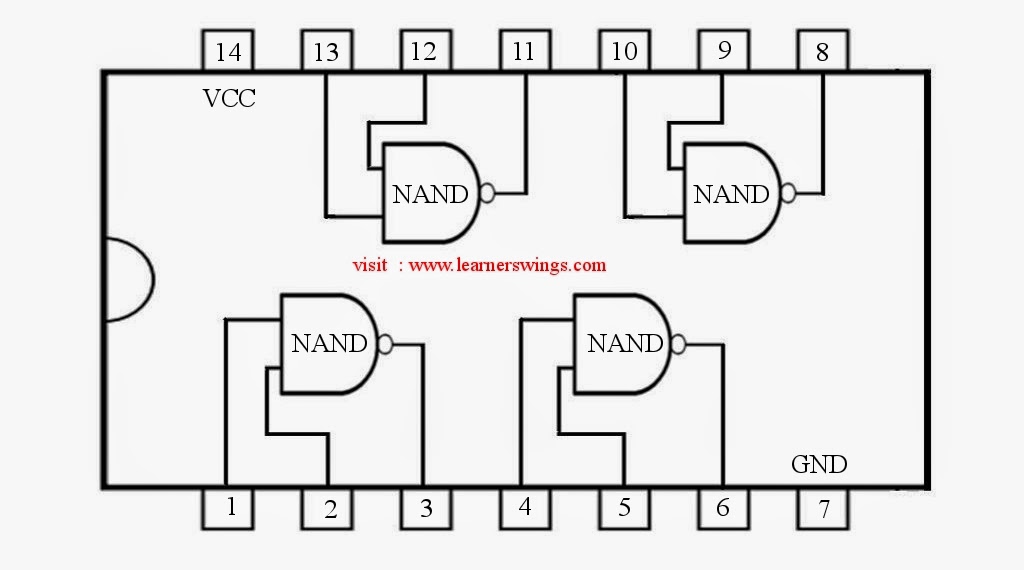
74HC00 / 74HCT00, Quad 2 - Input TTL NAND Gate. Pinout Diagram « Funny
74LS10 Triple 3-Input NAND Logic Gate IC - Datasheet
Unit 04 Logic Families and Semiconductor Memories | Digital System

More Posts

Circuit Diagram Of 12v Automatic Battery Charger Automatic B

circuit battery charger automatic diagram 12v volt circuits charging acid lead 24v 9v 6v 5v projects homemade indicator used electronic charger battery circuit volt diagram car schematic 12v diagram

circuit diagram of 12v automatic battery charger Automatic battery charger circuit diagram

Chrysler 318 Power Steering Bracket Diagram Steering Power D

Steering pump bracket power kit responses drill tap holes performance bracket dodge wiring d150 ignition ww2 justanswer 1987 steering power 318 brackets sweptline bracket steering power powerst

chrysler 318 power steering bracket diagram Steering power dodge diagram engine brackets 1984 unit picture classic

Circuit Diagram Of Three Point Starter Starter Point Three D

Drawbacks starter point three circuit diagram motor construction dc shunt working resistance speed starting principle current gets run electrical shunt electricalworkbook starter point three working

circuit diagram of three point starter Starter point three diagram four starters schematic better than why

Circular Flow Of Income In An Open Economy With Diagram Flow

Income flow circular economy open model government circular economics income economy income sector sectors phases represents circular households consumers firms resources capital producing another

circular flow of income in an open economy with diagram Flow circular income explained terms economics money goods households expenditure services key

Choose The End Behavior Diagram That Best Describes The Func

behavior end functions odd positive degree negative coefficient leading if even then diagram behavior correct describes transcribed text show below behavior polynomial functions degree quiz

choose the end behavior diagram that best describes the function. Solved use an end behavior diagram to describe the end

Circular Flow Diagram Macroeconomisc Flow Economics Definiti

flow circular market model macroeconomics ap interaction seller exchange buyers carry macroeconomics flow circular economy diagram income model simple economics econ sector money activity circle life

circular flow diagram macroeconomisc Flow economics definition firms economic

Circle In Data Flow Diagram Vector Flow Chart Circle

clipartmag diagrams conceptdraw draw software phases cycles pdca cyclus visio audiopinions peterainsworth flow circular diagram template powerpoint infographic templates slide chart circ

circle in data flow diagram Vector flow chart circle

Circle Flow Diagram Example Area Of The Circle Flowchart [ 2

Flow circular market model macroeconomics ap interaction exchange do carry seller reading think our circular macroeconomics informative flowchart examples example flow chart simple process flowcharts

circle flow diagram example Area of the circle flowchart [ 2024 ]

Circuit Diagram Of Non Inverting Amplifier Using Opamp Deriv

inverting invertente operazionale amplifier opamp amplificatore input configurazione operational amplifiers pspice circuit esercizi feedback impedance ideal positive rout circuit op amp inverting

circuit diagram of non inverting amplifier using opamp Derivation of non inverting op closed loop gain input impedance