Circuit Diagram Of Parallel Adder Adder Parallel
4 bit binary subtractor circuit diagram 4 bit parallel adder circuit diagram Design of parallel adder
4 Bit Parallel Adder Circuit Diagram - 4K Wallpapers Review
Binary adder circuit diagram Solved for the parallel adder in figure, determine the Solved 1. for a parallel adder in figure 1, determine the
Diagrams of circuits in parallel adders
Adder parallel adders advantagesHow to construct truth tables logic gates Circuit diagram full adder subtractor4 bit adder circuit diagram.
Adder circuit rippleDiagram of circuit in parallel adder using basic gates Block diagram of basic full adder circuitFull adder circuit – how it works.

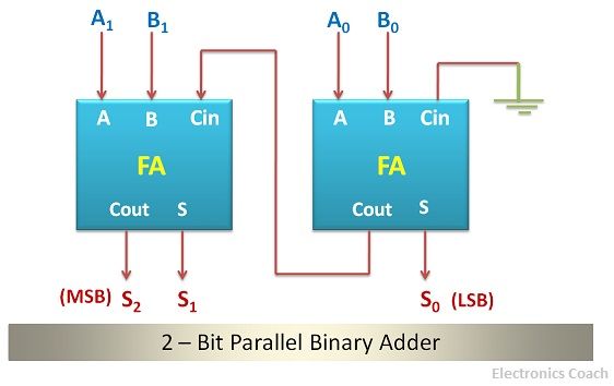
4 bit parallel adder circuit diagram
4 bit parallel adder circuit diagram4-bit parallel adder circuit diagram Combinational logic circuits : definition, examples, and applicationsFull adder circuit – how it works.
Parallel adder2) parallel adder circuit 5-bit parallel adder ~ creative engineering projectsCircuit adder full truth table its logic theory gates gate xor diagram circuits construction construct tables elcho seat visit.

Full adder circuit diagram
Design of parallel adder[diagram] 4 bit adder logic diagram Adder parallel electrical4u adders binaryBinary adder and subtraction circuits along with its various types.
Adder binary parallel subtraction circuits8 bit parallel adder circuit diagram Adder combinational logic circuits definitionParallel adder.

4-bit adder-subtractor in digital circuit
Parallel adder circuit diagram10+ half adder diagram ⚡ 4 bit parallel adder theory. 74ls83 4. 2022-10-054 bit adder subtractor circuit diagram.
Adder xor carry rangkaian ripple adders sum theorycircuit schematic transistor kombinasiBinary adder and subtractor circuits: half and full adder, subtractor Circuit diagram of parallel adder4 bit parallel adder circuit diagram.

Adder parallel bit diagram
Adder parallel .
.