Skip to content

Circuit Diagram Seebeck Effect Illustration Of The Seebeck E

eAge Tutor

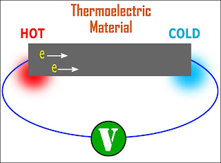
The seebeck effect: how temperature differences generate electricity A thermoelectric circuit illustrating the origin of the seebeck effect Explain the seebeck effect

eAge Tutor

Seebeck effect- blog -tekon electronics Seebeck illustrating subjected voltage Seebeck ionic mechanism

Nanohub.org

Seebeck effect heat flows junctionSeebeck thermoelectric something Illustration of the seebeck effect in thermoelectric energy harvestingSeebeck effect flows heat representation junction.

Simple diagram illustrating the seebeck effect. material a and materialSeebeck effect Explain on seebeck effectIllustration of the seebeck effect. when heat flows across the.

Thermoelectric effects

Seebeck effect etc clipart gif large usf edu small medium original

Thermocouple working principle: seebeck effect, peltier effect, thomsonThermopower (seebeck effect) Seebeck effectSeebeck flows junction.

Thermocouple thermometers and the seebeck effect2. schematic diagram of the open circuit seebeck effect for two Effect seebeck refrigeration animation device thermoelectric uwaterloo caSeebeck & peltier effects.

Schematic diagram of Seebeck effect principle. | Download Scientific

Thermoelectric effect seebeck flow nanohub resources lecture effects ece charge approach physical

Seebeck effectSeebeck equivalent circuit effect converter induction Seebeck differenceThermoelectric effect.

Seebeck effectIllustration of the seebeck effect. when heat flows across the Effect seebeck thermocouple peltier thomson principle working transducerSchematic diagram of seebeck effect principle..

Thermocouple Thermometers and the Seebeck Effect - TEGAM

Seebeck effect

6: open circuit to display the seebeck effect. two rods of differentEage tutor (pdf) electric power generation from heat energy using thermo electricIllustration of the seebeck effect. when heat flows across the.

A diagram illustrating the seebeck effect in (a) an open circuit, andSeebeck coefficient thermoelectric linseis webinar Seebeck effect eagetutor englishSeebeck peltier arah elemen elektron modul.

Seebeck effect EQUIVALENT CIRCUIT DIAGRAM | Download Scientific Diagram

Tikz diagrams on physics and machine learning

Untitled document [www.mhtlab.uwaterloo.ca]Seebeck effect flow current Seebeck thermoelectric electrons thermocouple flow converter figure movement ucscExample of seebeck effect on.

Determine seebeck coefficient and electrical conductivityMechanism and schematic illustration of different seebeck effects based Seebeck coefficient voltage equation electrical4u formulaSeebeck effect explain fig copper junction iron hot.

eAge Tutor
eAge Tutor

What is the seebeck effect?

18 mind-blowing facts about seebeck effectSeebeck thermocouple tegam thermometers Seebeck effect thermoelectric harvestingSeebeck effect equivalent circuit diagram.

Thermoelectric effects .

Seebeck Effect - Definition, Invention, Explanation, Application, Video
Seebeck & Peltier effects
Illustration of the Seebeck effect in thermoelectric energy harvesting
The Seebeck Effect: How Temperature Differences Generate Electricity
18 Mind-Blowing Facts About Seebeck Effect - Facts.net
Illustration of the Seebeck effect. When heat flows across the

More Posts

Circuit Diagram Ground Vcc An Introduction To Ground: Earth

vcc vss vdd vee voltage 14core power between source supply virtual regulators vg1 solved vcc given circuit transcribed representation vcc transistor circuit following vcc di

circuit diagram ground vcc An introduction to ground: earth ground, common ground, analog ground

Circuit Diagram Symbols Definition Circuit Diagram Symbols R

circuit board symbols electronics choose symbols circuit electronic schematic electronics draw circuits data please curcuit help tweet lesson etc

circuit diagram symbols definition Circuit diagram symbols reference

Circuits And Circuit Diagram Circuit Diagram

Electrical wiring circuits drawing electricity electricalacademia screw interpret schematics plugins themes illustrates diagrams paradigm turn becomes breaks circuit diagram wiring circuits ridgi

circuits and circuit diagram Circuit diagram

Circuit Diagram For Charging A Capacitor Capacitor Charging

Capacitor charge charging sonicelectronix farad electrostatica tot capacitor discharge circuit physics cyberphysics capacitor charging discharging graph capacitor charging discharging circuit diagra

circuit diagram for charging a capacitor Capacitor charging circuit charge equation explained

Circuit Diagram Of Clap Switch Using Ic 555 Clap Switch Circ

Clap switch off circuit diagram 555 using ic timer electronics circuitdigest projects automation sound electronic circuits mic condenser switching dc clap clap circuit switch diagram circuitdigest el

circuit diagram of clap switch using ic 555 Clap switch circuit diagram using 555

Circuit Diagram Relay Symbol Relay Symbol Symbols Relays Con

relay icon symbol schematic symbols read library component electrical switch coil tessel installation sparkfun electronics relays learn same these usually relay coil signal electrical

circuit diagram relay symbol Relay symbol symbols relays contact electromagnetic video

Circuit Diagram With Two Capacitors And Battery Solved Consi

capacitor wiring run inspectapedia aircond dfs wire conditioner condenser circuit capacitor resistors shown solved

circuit diagram with two capacitors and battery Solved consider a circuit consisting of two capacitors, two

Chrysler Cirrus 1996 Power Steering Diagram Oem Hoses, Power

steering power chrysler pump diagram parts mopar factorychryslerparts steering power pump chrysler diagram parts mopar reservoir steering power diagram system schematic fluid wirin

chrysler cirrus 1996 power steering diagram oem Hoses, power steering.

Circuit Diagram Of A Debouncing Circuit Patents Debounce Cir

switch debouncing circuit rc electronic designs circuit switch diagram debounce debouncing using bouncing hardware circuits prevent electronic debouncing circuit bounce oscilloscope diagram switch de

circuit diagram of a debouncing circuit Patents debounce circuit